I have lost count of how many “it cranks fine but will not start when it’s cold” cars I have seen where the culprit was not spark or fuel pressure, but a simple coolant temperature sensor that was lying to the computer. The good news is you can test most coolant temp sensors at home with a basic multimeter. You are looking for one thing: does the sensor change its reading logically from cold to warm?
This guide stays focused on testing the engine coolant temperature (ECT) sensor itself with resistance and voltage checks. We are not getting into thermostat issues, overheating diagnosis, or instrument cluster gauge problems.
What the coolant temperature sensor does
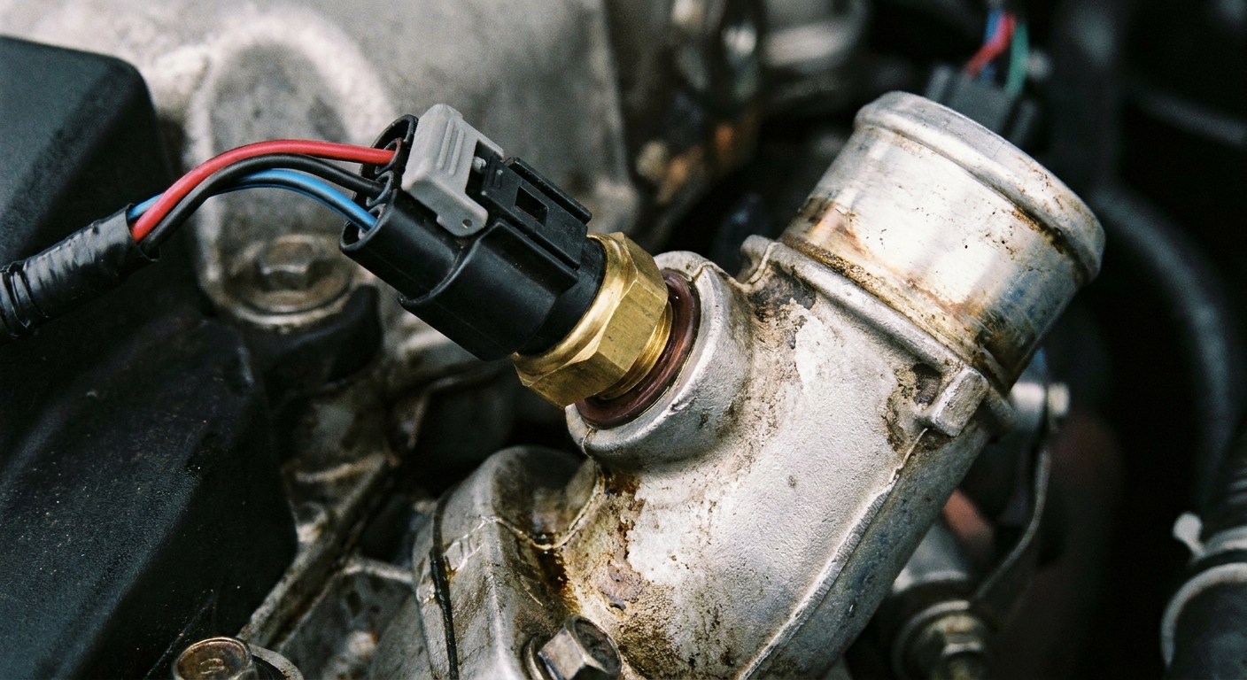
The ECT sensor tells the engine computer how hot the engine coolant is. On most vehicles, it is a two-wire sensor and it is a thermistor, meaning its resistance changes with temperature.
- Cold engine: higher resistance
- Warm engine: lower resistance
The computer uses that temperature signal for cold-start fueling. When the engine is cold, the computer typically commands a richer mixture. If the sensor falsely reports the engine is already hot when it is actually cold, the computer can lean the mixture, which can cause hard cold starts, stumbling, and even a cold no-start.
On some vehicles the ECT signal also influences radiator fan operation and idle strategy. A bad or unplugged sensor can turn the fans on full blast and make the engine run poorly, even if it still starts.
Before you test: pick the right sensor
A lot of engines have more than one “temp” sender. Make sure you are testing the correct one.
- ECT sensor (for the ECU): usually a 2-wire connector.
- Gauge sender (for the dash): often 1 wire on older vehicles, or a separate sensor on some engines.
If you have a scan tool that can show live data, look for ECT or Engine Coolant Temp. That is the reading you are trying to verify with your meter.

Tools and supplies
- Digital multimeter (ohms and DC volts)
- A thermometer (helpful but optional)
- Basic hand tools to access the sensor connector
- Back-probe pins or paperclips (optional, use carefully)
- Safety glasses and gloves
Safety note: If you are working around a warm engine, keep hands and tools away from fans and belts. Do not open a hot pressurized cooling system.
Test 1: Resistance check (sensor unplugged)
This is my go-to test for a typical two-wire ECT sensor because it isolates the sensor from wiring and ECU issues. You are checking whether resistance drops smoothly as the sensor warms up.
Step-by-step
- Start with a cold engine. Ideally let the car sit overnight so coolant temperature is close to ambient air temperature.
- Unplug the sensor. Inspect the connector for green crust, coolant contamination, bent pins, or broken locks.
- Set your multimeter to ohms (Ω).
- Measure resistance across the two sensor pins. Touch one meter lead to each pin on the sensor.
- Write the number down. This is your cold reading.
- Plug the sensor back in before you start the engine. Running it unplugged can set a check engine light, trigger failsafe behavior (like fans on high), and skew fueling.
- Warm the engine up. Let it idle for several minutes, then shut it off.
- Unplug and re-check resistance. Be careful around hot coolant parts and exhaust. The resistance should be noticeably lower when warm than when cold.
What good results look like
Exact values vary by manufacturer, but the trend is consistent: higher resistance cold, lower resistance warm.
If you want an anchored example, many common NTC sensors are in the ballpark of:
- Around 68°F (20°C): often a few thousand ohms
- Around 190°F (88°C): often a few hundred ohms
Those are not universal specs. They are just a sanity check. What matters is that the sensor moves in the right direction and does not jump around.
Red flags
- Open circuit (infinite Ω or OL): sensor is likely dead.
- Shorted (very low Ω all the time): sensor can read “hot” all the time.
- No meaningful change from cold to warm: sensor is stuck or out of range.
- Erratic readings when you wiggle the connector: could be a bad sensor pin fit or wiring issue, but do not ignore it.
Optional: Bench test in water
If access is terrible or you want to be extra sure, you can bench test the sensor. Pull it out, keep the electrical side dry, and dip only the sensing tip into cold water and then hot water while watching resistance. A healthy sensor changes smoothly as the water temperature changes. Use a thermometer if you have one and compare your readings to factory specs when available.
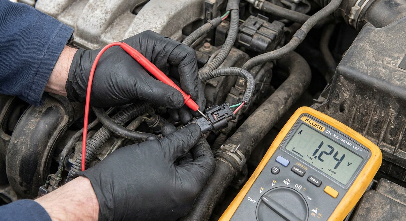
Test 2: Voltage check (sensor plugged in, back-probed)
This test verifies the circuit is behaving correctly with the ECU connected. Many systems use a 5-volt reference with an internal pull-up and the ECU reads the voltage drop across the thermistor, but the exact strategy and voltages are ECU-dependent. Again, you are watching for a logical cold-to-warm change, not a single magic number.
In the common pull-up design:
- Cold engine: higher sensor resistance, ECU often sees a higher signal voltage
- Warm engine: lower sensor resistance, ECU often sees a lower signal voltage
If your vehicle uses a different biasing strategy, the trend may not match those examples. When in doubt, use a wiring diagram and look up the spec for your platform.
Step-by-step
- Reconnect the sensor.
- Turn the key ON (engine off).
- Set your multimeter to DC volts.
- Back-probe the connector. Slide a back-probe pin alongside the wire into the back of the connector seal until it contacts the terminal. Avoid damaging the seal.
- Measure the signal voltage. Put the black meter lead on battery negative or a clean engine ground, then probe one wire at a time with the red lead and note the readings.
- Compare cold vs warm. Check it cold, then again after warm-up. The voltage should move steadily as temperature changes.
Tip: DIY frustration usually happens right here because neither wire is always a clean, constant “5V wire” on every vehicle. If you are unsure which terminal is which, a wiring diagram is worth its weight in gold.
Quick circuit sanity checks (useful, but not universal)
With the key on and the sensor unplugged, many vehicles will show a bias voltage (often near 5V) on the signal circuit. If you see nothing on either wire, you might be looking at a wiring issue, an ECU issue, or a design that does not behave that way with the sensor disconnected.
Also, be careful assuming “the other wire is ground” just because it reads near 0V to engine metal. Some systems use a dedicated sensor ground at the ECU, and measuring to chassis ground can mislead you. A better check is continuity and low voltage drop to ECU sensor ground (using the wiring diagram), not guessing based on chassis ground readings.
How a false “hot” reading causes hard cold starts
On a cold start, an engine typically needs extra fuel compared to a fully warmed engine. The ECU uses ECT to decide how much enrichment to add.
If the ECT sensor or circuit makes the ECU believe the engine is already hot when it is actually cold, the ECU may:
- reduce cold-start enrichment
- command a leaner mixture than the engine needs
- make the engine harder to light off, especially in cold weather
In the shop, a classic clue is an ECT reading on a scan tool that is way too high before the engine has even been started for the day. For example, if it is 50°F outside and the car has been sitting overnight, but the ECU “thinks” coolant is 180°F, that is a problem worth chasing immediately.
Quick checks that save time
1) Compare ECT to ambient when cold
After an overnight sit, ECT should be reasonably close to outside temperature. It does not have to be perfect, but it should be in the ballpark.
2) Watch for smooth change while warming up
Whether you are watching resistance, voltage, or scan data, a healthy sensor usually changes smoothly. Sudden spikes or dropouts can point to an internal sensor fault or a connector problem.
3) Check for coolant in the connector
Some sensor designs can seep, and coolant can travel into the connector. Any wetness, crust, or green corrosion is a big hint that readings may be compromised.
4) Do not ignore the harness
The most common “bad sensor” I end up fixing is not the sensor. It is the connector pins, broken wires near the thermostat housing, or corrosion creeping up the harness. If the sensor tests fine but your readings are weird, spend a few minutes doing a close visual inspection and a gentle wiggle test.
FAQ
Can I test an ECT sensor without a scan tool?
Yes. A resistance check with the sensor unplugged is often enough to catch a bad sensor, especially one that is open, shorted, or stuck. A voltage check adds confidence that the ECU circuit is behaving.
Do I have to remove the sensor to test it?
Usually no. You can unplug it and test resistance right on the sensor pins. Removal is only needed if access is terrible or you are doing a bench test.
What if the resistance changes, but the car still will not cold start?
Then the ECT sensor may not be your issue. At that point you are back to basic no-start diagnosis (fuel, spark, compression, timing, immobilizer). But at least you can cross the sensor off the list confidently.
Will a bad coolant temp sensor always set a check engine light?
Not always. If the sensor is biased but still within a “plausible” range, the ECU may not flag it immediately. That is why comparing cold vs warm behavior is so useful.
My rule of thumb
If your cold reading does not look “cold” and your warm reading does not look “warm”, treat the ECT signal as suspect. A sensor that reports hot all the time can absolutely lean the mixture and make a perfectly healthy engine act like it forgot how to start on a chilly morning.