I have seen a lot of “cranks strong but won’t start” situations end up being a crankshaft position sensor problem, or a wiring or tone ring problem that looks like the sensor. The good news is you can do a pretty solid driveway test with a basic multimeter and a little patience.
This guide is focused on a crank-no-start (starter spins the engine, but it will not fire). If your car stalls while driving and restarts, or it won’t start after you just replaced the crank sensor, those are different troubleshooting paths.
What the crank sensor does
The crankshaft position sensor (CKP) tells the engine computer two big things:
- Engine speed (RPM)
- Crank position so the computer knows when to fire spark and inject fuel
If the computer cannot see a crank signal while you are cranking, many vehicles will give you a true no-start because it will not trigger ignition and often will not pulse the injectors.
Quick symptoms
- No RPM signal while cranking (more on the tach in a minute)
- Intermittent or no spark and no injector pulse during cranking
- Crank-no-start with a stored CKP code on some cars (not always)
- Starts only when the sensor cools down (more of a stall-then-restart story, which is a different article)
Important: a bad CKP sensor is common, but so are broken wires, corroded connectors, incorrect air gap, metal debris on magnetic sensors, and damaged tone rings.
Tools you will want
- Digital multimeter (one that can read AC voltage in the millivolt range helps)
- Back-probe pins or thin paperclips (be gentle)
- Basic hand tools to access the connector and sensor
- Flashlight
- Helper to crank the engine while you watch the meter
If you have a scan tool that shows live data (engine RPM while cranking), that is a bonus, but I am keeping this method multimeter-first.
Step 1: Confirm crank-no-start
Before you blame the crank sensor, make sure:
- The engine is cranking at a normal speed (not a weak battery slow crank)
- There is fuel in the tank (it happens)
- The immobilizer or security light is not doing something obvious
Then move on to the CKP checks.
Step 2: Identify sensor type
Most crank sensors fall into two families:
- 2-wire magnetic (variable reluctance): generates its own AC voltage signal while cranking.
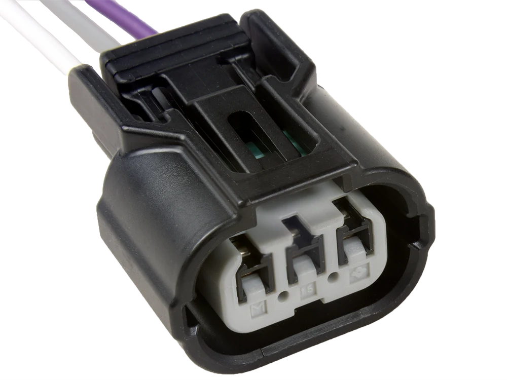
- 3-wire Hall effect: uses a power feed and ground, and it switches a digital signal on the third wire.
A quick clue: if it has two wires, it is usually magnetic. If it has three wires, it is usually Hall effect. There are exceptions, so if you have wiring info for your exact vehicle, use it.
Step 3: Check the connector
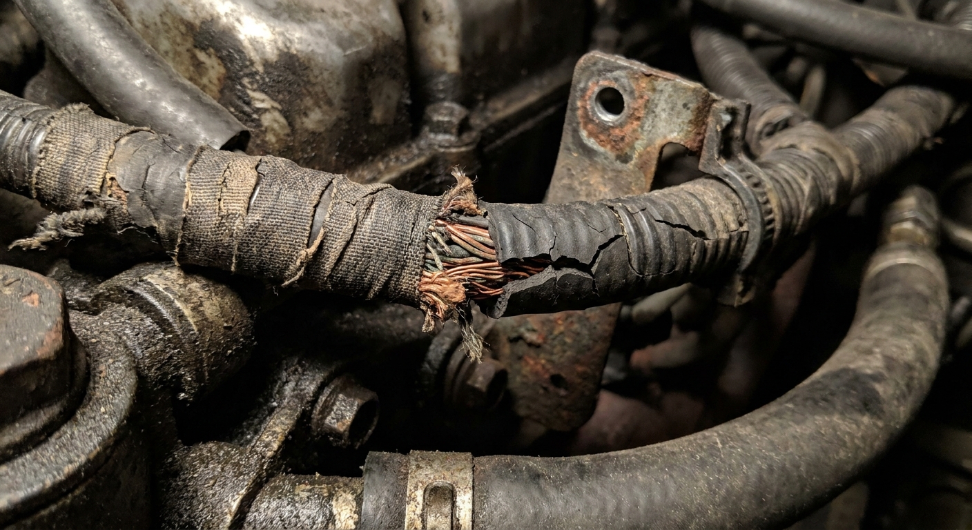
I cannot count how many “bad sensors” were actually connector issues. With the key off, unplug the sensor and inspect:
- Green or white crust on terminals (corrosion)
- Oil saturation inside the connector
- Spread or pushed-back pins
- Broken locking tab that lets the plug wiggle loose
- Harness rubbing on a belt, pulley, axle, or exhaust
Step 4: Power and ground
If your crank sensor has three wires, do this before you condemn the sensor.
4A: Check for reference voltage
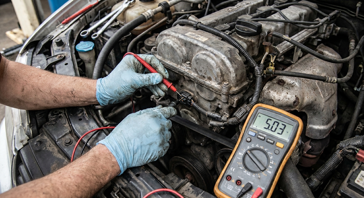
Set your multimeter to DC volts. Back-probe the connector on the harness side (not the sensor side) with the key on, engine off.
- Many Hall sensors get 5 volts reference.
- Some get 8 to 12 volts depending on design.
If you have 0 volts on the power feed wire, you do not have a bad crank sensor yet. You have a power supply problem (wiring, fuse, relay, ECU feed).
4B: Check ground with voltage drop
A ground can look fine on an ohms check and still fail under load. My favorite driveway method is a voltage drop test, and the meter lead placement matters.
- Put the meter on DC volts.
- Connect the black lead to battery negative.
- Back-probe the sensor ground wire with the red lead.
- Crank the engine.
You want a low reading, typically under about 0.2 volts. If you see a higher number while cranking, that ground circuit has too much resistance (corrosion, broken strands in the wire, poor splice, loose ground point), and the sensor may never signal correctly.
Tip: If you want to double-check yourself, put the red lead on battery negative and the black lead on the sensor ground. You should see the same voltage drop, just with the polarity flipped.
Step 5: Test signal while cranking
This is the part most people skip, and it is the part that actually proves whether the computer is getting a crank signal.
Option A: 2-wire magnetic sensor
Magnetic sensors generate AC voltage while the engine turns.
- Leave the sensor plugged in if you can safely back-probe. If not, you can test unplugged at the sensor pins, but an in-circuit test is better.
- Set your meter to AC volts.
- Back-probe the two sensor wires.
- Have a helper crank the engine.
What should you see? It varies by vehicle and meter quality, but during cranking you will often see something like 0.2 to 1.5 VAC, sometimes more. The key is that it should not be dead flat at 0.00.
If you see no AC voltage at all while cranking, suspect:
- Failed sensor
- Sensor too far from the tone ring (air gap issue)
- Broken tone ring teeth
- Open circuit in the wiring
Option B: 3-wire Hall effect sensor
Hall sensors output a digital on-off signal. A basic multimeter is not as perfect as an oscilloscope here, but you can still learn a lot.
- Keep it plugged in and back-probe the signal wire.
- Set meter to DC volts.
- Connect black lead to a known good ground.
- Crank the engine.
Depending on design, you may see the voltage toggle or at least fluctuate while cranking (for example bouncing between low and high). If it stays pinned at 0V or pinned at the full reference voltage the entire time, and you have verified power and ground are good, that is a strong clue the sensor is not producing a usable signal or the tone ring is not being read.
If you happen to have a meter with a frequency (Hz) setting, you can also try reading frequency while cranking. A changing Hz reading indicates the sensor is producing pulses.
Step 6: Resistance check
A resistance test can catch an open or shorted magnetic sensor, but it is not the final word.
For 2-wire magnetic sensors
With the sensor unplugged, set your meter to ohms and measure across the two sensor pins.
- Many read somewhere in the 200 to 2,000 ohms range.
- An open circuit (OL) usually means the sensor is bad or the internal coil is broken.
- A dead short (near 0 ohms) is also a bad sign.
Because specs vary wildly, I treat this as a sanity check. If it is in range, it still could be weak under cranking. That is why the AC output test matters.
For 3-wire Hall sensors
Resistance testing is usually not helpful. Focus on power, ground, and signal switching.
Step 7: Check the tone ring
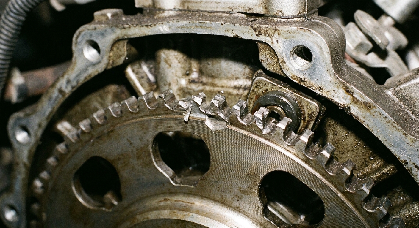
You can have a perfectly good crank sensor that cannot read because the tone ring is damaged, shifted, or packed with debris.
The tone ring might be:
- On the crank pulley
- Behind the harmonic balancer
- On the flexplate or flywheel
- Integrated into the crankshaft or timing gear
What to look for
- Missing or cracked teeth
- Wobble from a damaged balancer or loose mounting
- Rust swelling (common on some press-fit reluctor rings)
- Metal fuzz stuck to a magnetic sensor tip
If you can access it, rotate the engine by hand (breaker bar on the crank bolt, key off) and visually inspect as much of the ring as you can.
Dead tach during cranking
On many vehicles, the tachometer gets its RPM information from the same crank signal the ECU uses. So if the tach stays completely dead while you crank, it can add weight to the suspicion that the ECU is not seeing an RPM signal.
Two big cautions from the shop floor:
- Some cars will still show no tach movement during cranking even when everything is fine.
- Some clusters get RPM from the ECU over the network, so a dead tach can also be a communication or cluster issue.
Use the tach as a clue, not a conviction. If you can read live data RPM on a scan tool, that is a better version of the same idea.
Common driveway mistakes
- Testing voltage with the connector unplugged and wondering why nothing changes
- Not back-probing safely and spreading terminals, creating a new problem
- Skipping power and ground checks and throwing a sensor at a wiring issue
- Ignoring oil leaks that fill the connector and wick into the harness
- Assuming a new sensor cannot be bad (it happens, but that is a different diagnostic story than this crank-no-start test)
When to stop
If you have verified:
- Good battery and cranking speed
- Good CKP power feed and ground (if applicable)
- No CKP signal output during cranking
- No obvious tone ring damage
At that point, I start thinking about deeper issues: harness faults under load, ECU problems, or mechanical timing problems. An oscilloscope test of the CKP and cam sensor signals together can save a lot of guessing.
FAQ
Can a crankshaft position sensor fail with no check engine light?
Yes. On a hard crank-no-start, the ECU may not be able to “see” enough signal to set a code, or the code may be pending only. Do not rely on the light alone.
Will a bad crank sensor cause no spark?
Very often, yes. If the ECU does not know engine speed and position, it may not trigger the ignition system or injector pulse.
Is there a fast way to confirm a crank signal without a meter?
A scan tool that shows RPM while cranking is a quick check. If RPM stays at 0 while cranking on a vehicle that normally displays it, that is a strong clue. It is still wise to follow up with wiring and sensor output checks to avoid misdiagnosis.